-0.95~140bar Pneumatic Pressure Pump MK-PC109

I. Features
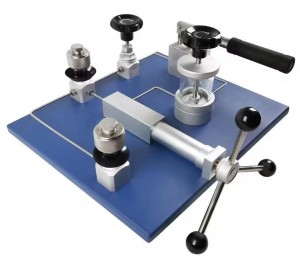
The MK-PC109 portable pneumatic pressure pump adopts an open, innovative integrated design for micro-pressure and medium-pressure applications. It features simple operation, stable pressure increase and decrease, fine adjustment (10Pa), easy maintenance, and low leakage. The carefully designed structure and effortless pressure generation process will make your calibration work more efficient.
II. Main Applications
It provides a stable and highly accurate gas micro-pressure, vacuum, and medium-pressure source for calibrating pressure (differential pressure) transmitters, pressure (differential pressure) sensors, precision pressure gauges, general pressure gauges, micro-pressure diaphragm pressure gauges, and other pressure instruments.
II. Technical
1. Model: MK-PC109
2. Pressure Range: (-0.95 to 140) bar
3. Medium: Air
4. Minimum Adjustment Increment: 10 Pa
5. Nominal Dimensions: 360mm × 204mm × 100mm
6. Weight: 5 kg
7. Pressure Connection: M20*1.5 (2 ports)
Ⅲ. Structure
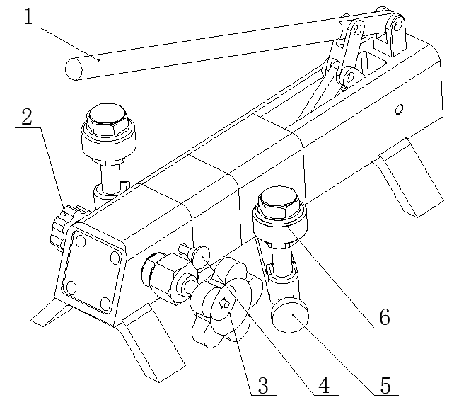
1. Push rod
2. Shut-off valve
3. Fine adjustment valve
4. Directional control valve
5. Pressure relief valve
6. Gauge connection rod
1. Positive Pressure Increase Process Testing
(1) Set the directional control valve 4 to the right position.
(2) Connect the standard instrument and the instrument under test to the two instrument connection ports 6 respectively.
(3) Close the pressure relief valve 5 clockwise.
(4) Rotate the fine-tuning handwheel 3 counterclockwise, withdrawing it to the furthest right end of its travel.
(5) Manually operate the pressure lever 1 for pre-pressurization. When the pressure value approaches the first test point, close the shut-off valve 2 clockwise.
(6) Use the fine-tuning handwheel 3 to precisely control the pressure to the first test point for testing.
(7) After completing the first test point, open the shut-off valve 2 counterclockwise.
(8) Repeat steps (4) to (6) to test the pressure at the remaining test points.
2. Positive Pressure Decrease Process Testing
After the pressure increase is completed, when pressure decrease testing is required, slowly rotate the fine-tuning handwheel 3 counterclockwise to perform the pressure decrease calibration.
3. Negative Pressure Decrease Process Testing
(1) Set the directional control valve 4 to the left position.
(2) Connect the standard instrument and the instrument under test to the two instrument connection ports 6 respectively.
(3) Close the pressure relief valve 5 clockwise.
(4) Rotate the fine-tuning handwheel 3 clockwise, advancing it to the furthest left end of its travel.
(5) Manually operate the pressure lever 1 for pre-pressurization. When the pressure value approaches the first test point, close the shut-off valve 2 clockwise.
(6) Use the fine-tuning handwheel 3 to precisely control the pressure to the first test point for testing.
(7) After completing the first test point, open the shut-off valve 2 counterclockwise.
(8) Repeat steps (4) to (6) to test the pressure at the remaining test points.
IV. Instructions for Use
1. Do not use this equipment at pressures exceeding its rated pressure.
2. Operate strictly according to the operating requirements, using gentle movements and avoiding excessive force.
3. After use, please seal all output ports and store the equipment in a clean and dry environment.
4. After the calibration process is complete, open stop valve 2 counterclockwise to prevent pressure lever 1 from malfunctioning during the next calibration.
5. Forcibly pressing down on the pressure lever may damage the internal sealing structure.
V. WARNING
All instruments to be tested must be cleaned to remove internal residual impurities before calibration.
Ⅶ.Problems& Solutions
| Problems | Reasons | Solutions |
| The lever cannot be pressed down. | The shut-off valve is not open. | Before use, open the shut-off valve. |
| Difficulty in applying pressure. | The pressure relief valve is not closed tightly. | Tighten the pressure relief valve. |
| Unstable pressure, excessively rapid descent. | (1) The meter head is not properly sealed or the sealing parts are damaged; | (1) Tighten the gauge head or replace the seal; |
| (2) The pressure relief valve is not closed tightly; | (2) Tighten the pressure relief valve; | |
| (3) Impurities in the pipeline affect the sealing effect. | (3) Repeatedly apply and release pressure to flush out impurities from the pipeline. |