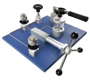
0-700bar /0-10000psi Hydraulic pressure pump MK-PC108

I.Features
The MK-PC108 portable hydraulic pump features a simple structure, is easy to carry, and is leak-proof. It employs a combination of lever pressurization and screw fine-tuning, providing stable and reliable pressure. It is the optimal choice for calibrating pressure transmitters, pressure switches, pressure gauges, and pressure sensors in laboratories or industrial settings from 0 to 700 bar. It meets the JB/T599—2005 industry standard for pressure gauge calibrators.
II. Tech
MODEL: MK-PC108
Pressure Range: (0~700)bar/ (0~10000) psi
Temperature Range: (5~50)℃
Humidity Range: <95%
Working Medium: Diisooctyl sebacate or deionized water
Minimum Adjustment: 10 kPa
Safety Pressure: Less than 1.5 times the maximum pressure
Dimensions: 375mm × 200mm × 150mm
Weight: 5kg
Pressure Connection: M20 × 1.5 quick-connect internal thread (2 pieces) or customized
Ⅲ. Main Applications
Ideal pressure source for calibrating various pressure transmitters, pressure switches, pressure gauges, and other pressure instruments and meters within the range of (0~200) bar, (0~400) bar, and (0~70) bar.
Ⅳ.Product Structure
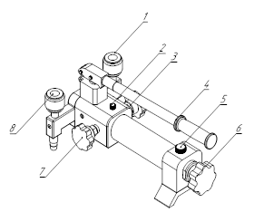
Note: 1—Gas unit; 2—Ventilation port; 3—Stop valve; 4—Pressure rod; 5—Oil filling port; 6—Fine adjustment handwheel; 7—Pressure relief valve; 8—Gas unit.
Ⅴ. Instructions for Use
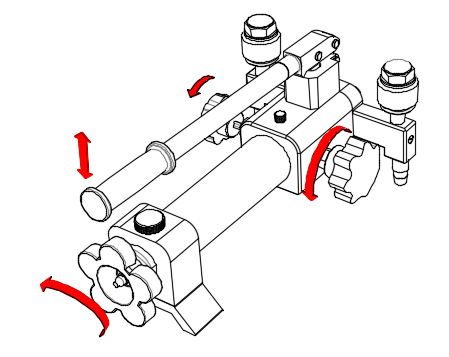
4.1 Pressure Boosting Test
Open the vent nut (2), connect the standard instrument and the instrument under test to the connectors (1) and (8) respectively, then close the pressure relief valve (7) clockwise, and rotate the fine adjustment handwheel (6) counterclockwise to pull it back about 30mm. Then use the pressure rod (4) to move up and down to pre-pressurize. When the value is close to the first test point, close the shut-off valve (3) clockwise, and use the fine adjustment handwheel (6) to precisely adjust to that point for testing. After the first test point is completed, continue to rotate the fine adjustment handwheel (6) to pressurize to the second test point, record the relevant data, and the second test point test is completed. Repeat this process to complete the pressure boosting test of other test points.
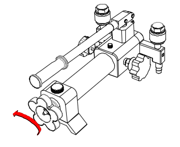
4.2 Pressure Reduction Process Detection After the pressure increase is completed, when pressure reduction detection is required, use the fine-tuning handwheel (6) to slowly rotate counterclockwise to perform pressure reduction process calibration. After the pressure reduction calibration process is completed, the shut-off valve (3) should be opened counterclockwise (otherwise the pressure rod (4) will not work properly during the next operation, and if it is forcibly pressed down, it will damage the internal sealing structure of the equipment).
Ⅵ. Warning
(1) All instruments and meters under test must be cleaned before calibration to remove internal residual impurities;
(2) Hydraulic pumps should be used within their rated pressure range as much as possible, and the safe pressure of the equipment must not be exceeded;
(3) During use, the liquid/air filling button should always be in the open position;
(4) The liquid level of the pressure transmission medium should be between 1/4 and 3/4 of the oil cup;
(5) If impurities or other contaminants are found in the hydraulic oil in the oil cup, the medium should be replaced promptly (it is recommended to replace it every 3 to 6 months);
(6) All rotating handwheels and quick couplings should be operated strictly according to the operating requirements. The movements should be gentle, and excessive force should not be used;
(7) The exposed threaded parts should be kept clean and lubricated. If contaminated, please clean them promptly;
(8) After use, please seal all output ports and store them in a clean and dry environment.
(9) During transportation, use the plug to lock the quick coupling, close the liquid/air filling button, and fully screw in the pre-pressure and pressurization adjustment handwheels.
Ⅶ. Problems & Solutions
| Problems | Reasons | Solutions |
| The lever cannot be pressed down. | The shut-off valve is not open. | Before use, open the shut-off valve. |
| Difficulty in applying pressure. | The pressure relief valve is not closed tightly. | Tighten the pressure relief valve. |
| Unstable pressure, excessively rapid descent. | (1) The meter head is not properly sealed or the sealing parts are damaged; | (1) Tighten the gauge head or replace the seal; |
| (2) The pressure relief valve is not closed tightly; | (2) Tighten the pressure relief valve; | |
| (3) Impurities in the pipeline affect the sealing effect. | (3) Perform multiple pressurization and depressurization operations to remove impurities from the pipeline. If there are significantly too many impurities in the hydraulic oil, replace the hydraulic oil. |
Products categories
-

MK-PC101 Hydraulic Pressure Test Pump 0-700bar
-

MK-PC102 Hydraulic comparison test pump
-

MK-PC103 Portable Pneumatic Pressure Test / Cal...
-

MK-PC104 0-1000bar Portable Pressure Calibratio...
-

MK-PC105 Pneumatic Pressure Test Pump -0.95~16...
-
MK-PC106 Hydraulic pressure comparators /pump/ ...
-

MK-PC107.Pheumatic pressure pump 0-0.7Mpa 0-7ba...