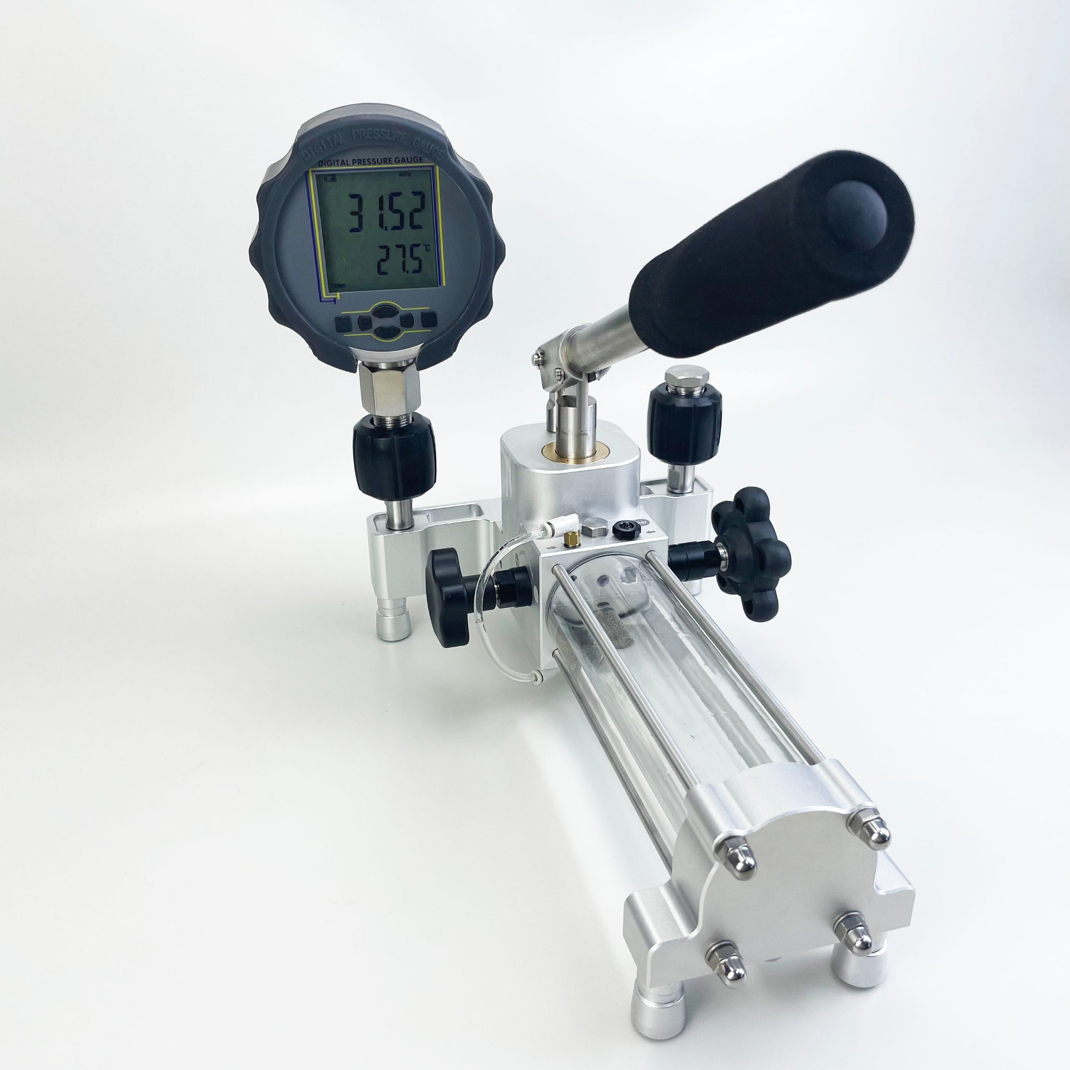
As a simple and convenient hydraulic power source, ultra-high pressure manual hydraulic pump is widely used in many fields such as shipbuilding industry, coal mining machinery, petrochemical, metallurgy, electric power and heavy machinery. And with its small size, light weight, easy to carry, strong safety and other advantages are accepted by the majority of users.
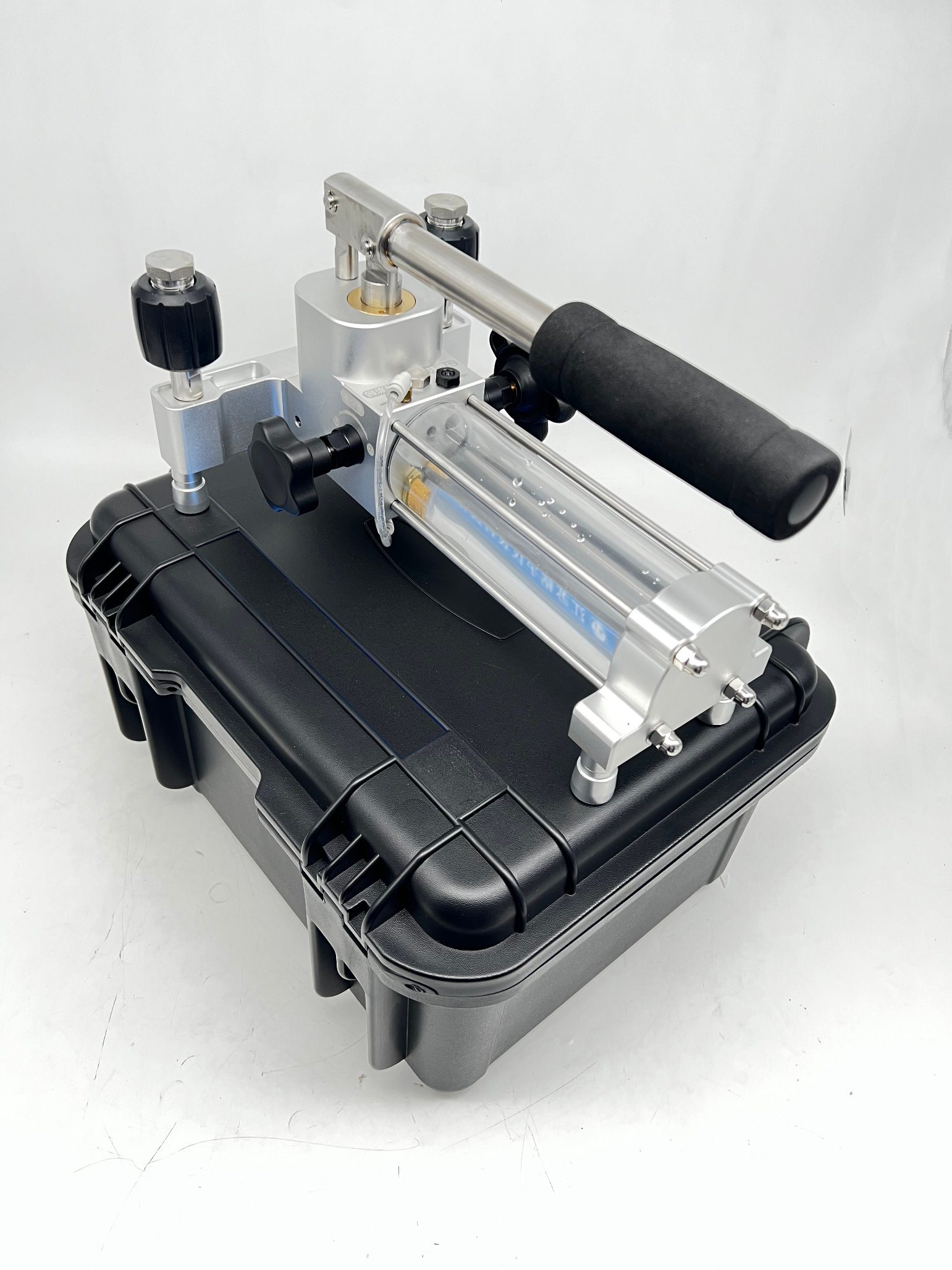
MP series ultra-high pressure manual hydraulic pump, the working pressure is 100~300MPa; there is a pressure reducing valve inside, in order to prevent the pressure overload, there is also a safety relief valve in the pump; the secondary flow design, the displacement at the primary low pressure is 33CC, the second The displacement at high pressure is 1.6CC; under the condition of constant power, low-pressure large-flow oil supply, high-pressure small-flow oil supply, saving time and improving efficiency. The overall size is 585*120*170mm, and the total weight with oil is about 11Kg. The use shows that this pump is convenient and flexible, low labor intensity, durable, and is an ideal ultra-high pressure hydraulic power source.
Principle
The function of the manual hydraulic pump is to convert the mechanical energy of the power machine (such as an electric motor and an internal combustion engine) into the pressure energy of the liquid.
Working principle: The cam is driven by the motor to rotate. When the cam pushes the plunger to move upward, the sealing volume formed by the plunger and the cylinder is reduced, and the oil is squeezed out from the sealing volume and discharged to the required place through the one-way valve. When the cam rotates to the descending part of the curve, the spring forces the plunger downward to form a certain degree of vacuum, and the oil in the tank enters the sealing volume under the action of atmospheric pressure. The cam makes the plunger rise and fall continuously, the sealing volume decreases and increases periodically, and the pump continuously absorbs and discharges oil.
Existing Profile
The existing manual hydraulic pumps on the market are generally plunger pumps, with single-stage and double-stage forms. All its valves are usually concentrated on the plunger pump, and the structure is relatively compact; the reversing valve and the plunger pump are divided into two independent parts, but they can be used in combination. The structure of the single-stage plunger pump is relatively simple, and its principle is shown in Figure 1; the two-stage plunger pump has two different structural forms, and its principle is shown in Figure 2 and Figure 3.
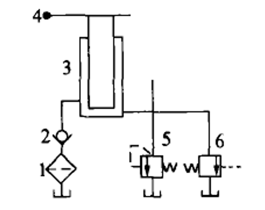
When the handle 4 is lifted up, the hydraulic oil enters the lower chamber of the plunger 3 through the filter 1 and the one-way valve 2, and the hydraulic pump sucks oil; when the handle 4 moves downward, the plunger 3 supplies oil to the system. Valve 5 is a safety valve, and valve 6 is an unloading valve. The single-stage pump is an intermittent pressurized oil supply, and the displacement cannot be adjusted. It can only be low-pressure large flow or high-pressure small flow; generally low and medium pressure pumps.
Introduction to the principle of two-stage plunger pump
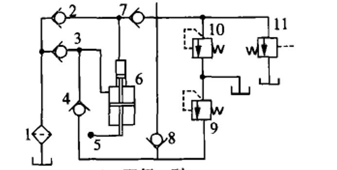
Figure 2 is a schematic diagram of a two-stage I-type hand pump. Lift the handle 5, and the hydraulic oil enters the large and small cavities of the plunger through filter 1, check valves 2 and 3 respectively. When the handle 5 is pressed, there are two situations: when the system is at low pressure, the check valves 4, 7, and 8 are opened, and the dual pumps supply oil to the system at the same time, and the flow rate is the largest; when the system is at high pressure, the sequence valve 9 is opened (the sequence valve is set. The constant pressure is generally 1 MPa), the check valve 8 is closed, the low-pressure oil of the large pump is directly returned to the oil tank, and the small pump alone supplies oil to the system with a small flow. The valve 10 is a constant pressure valve, and the valve 11 is an unloading valve. The two-stage I-type hand pump provides low-pressure, large-flow, high-pressure, small-flow, and intermittent oil supply.
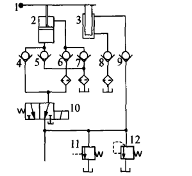
Figure 3 is a schematic diagram of a two-stage II type manual pump, the valve 11 is a constant pressure valve, and the valve 12 is an unloading valve. In the low pressure area, when the handle 1 moves upward, oil is supplied to the lower oil chambers of pumps 2 and 3, and oil is supplied to the upper chamber of pump 2. When the handle 1 moves downward, the upper cavity of the pump 2 enters oil, and the lower cavities of the pumps 2 and 3 supply oil to the system; in the low pressure area, the pump can continuously supply oil to the system. When entering the high pressure area, the system pressure increases, and the hydraulic control reversing valve 10 works in the right position, so that the oil circuit composed of pump 2 and check valves 4, 5, 6, and 7 is unloaded, and pump 3 and check valves 8 and 9 are unloaded. The composed oil circuit supplies oil to the system. Compared with the two-stage type I, the two-stage type II manual pump can achieve continuous oil supply, improve efficiency and save time, but it is also low-pressure, large-flow, high-pressure, small-flow oil supply.
Repair
1. Find the cause of the failure from the following three points during maintenance, and improve the system:
1. Check the internal leakage of the boom cylinder:
The easiest way to do this is to raise the boom and see if it has a noticeable free fall. If the drop is obvious, dismantle the oil cylinder for inspection. If the sealing ring is found to be worn, it should be replaced.
2. Check the control valve:
First clean the safety valve, check whether the valve core is worn, if worn, it should be replaced. If there is still no change after the safety valve is installed, check the wear of the control valve spool again.
3. Measure the pressure of the hydraulic pump:
If the pressure is low, adjust it, and the pressure still cannot be adjusted up, indicating that the hydraulic pump is seriously worn.
2. The main reasons for the inability to lift the boom with load are:
1. The hydraulic pump is seriously worn. When running at low speed, the internal leakage of the pump is serious; when running at high speed, the pump pressure is slightly increased, but due to the wear and internal leakage of the pump, the volumetric efficiency drops significantly, and it is difficult to reach the rated pressure. The long-term operation of the hydraulic pump aggravates the wear and the oil temperature rises, which causes the wear of the hydraulic components and the aging and damage of the seals, the loss of the sealing ability, the deterioration of the hydraulic oil, and finally the failure occurs.
2. The selection of hydraulic components is unreasonable. The specifications of the boom cylinder are 70/40 non-standard series, and the seals are also non-standard parts, so the manufacturing cost is high and the replacement of the seals is inconvenient. The small cylinder diameter of the boom cylinder is bound to increase the set pressure of the system.
3. The hydraulic system design is unreasonable. It can be seen from Figure 2 that the control valve and the full hydraulic steering gear are connected in series with a single pump, the set pressure of the safety valve is 16MPa, and the rated working pressure of the hydraulic pump is also 16MPa. Hydraulic pumps often work under full load or long-term overload (high pressure) conditions, and the system has hydraulic shocks. If the oil is not changed for a long time, the hydraulic oil is contaminated, which aggravates the wear and tear of the hydraulic pump, so that the pump casing of the hydraulic pump bursts. such failure).
Product Improvement
1. Improve the hydraulic system design.
After many demonstrations, the advanced priority valve and load-sensing full-hydraulic steering gear are finally adopted. The new system can give priority to allocating flow to it according to the steering requirements. No matter the size of the load or the speed of the steering wheel, it can ensure sufficient oil supply, and the remaining part can be guaranteed. It can be fully supplied to the working device circuit, thereby eliminating the power loss caused by excessive oil supply in the steering circuit, improving the system efficiency and reducing the working pressure of the hydraulic pump.
2. Optimize the design of the boom cylinder and hydraulic pump to reduce the working pressure of the system.
Through optimized calculation, the boom cylinder adopts standard series 80/4. The displacement of the hydraulic pump is increased from 10ml/r to 14ml/r, and the set pressure of the system is 14MPa, which meets the lifting force and speed requirements of the boom cylinder.
3. Pay attention to the correct use and maintenance of the loader during use, add or replace hydraulic oil regularly, maintain the cleanliness of the hydraulic oil, and strengthen daily inspection and maintenance.
Scope of application
Electric power, railway, rescue, construction and other industries operate on field construction sites, providing power for construction equipment such as cutters, hydraulic pliers, punching machines, etc.
Static and burst testing for fittings, hoses, valves, pressure vessels, cylinders, etc.

Static and dynamic test safety valve calibration after repair of aerospace accessories
Bubbling test in water for valves and wellhead devices
Air pressure regulator inspection
Automotive brake system testing
Communication cable inflatable equipment
Price
There are two kinds, domestic and foreign. Compared with other countries, the price of this product in China is relatively low.
Post time: Jul-15-2022